Preparing the Simulation of an Energy System
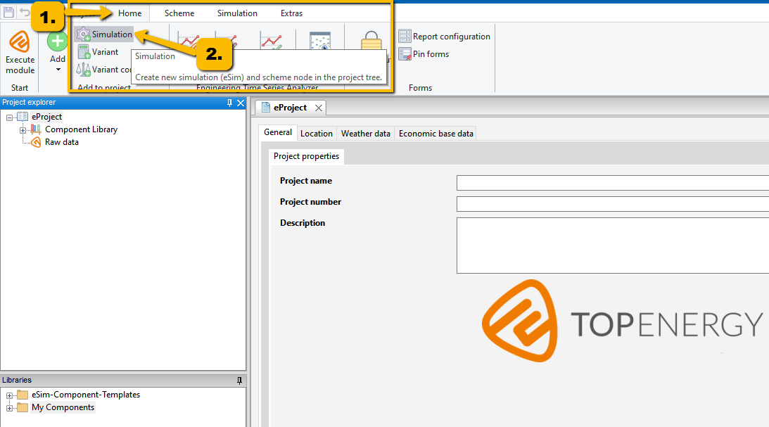
First create a ![]() Simulation node. Later on, you can use this to start the system simulation.
Simulation node. Later on, you can use this to start the system simulation.
Click the button ![]() Simulation on the Home ribbon in the group Add to the project.
Simulation on the Home ribbon in the group Add to the project.
An ![]() Simulation node with a subordinated
Simulation node with a subordinated ![]() Scheme node is added to the project and shown in the Project explorer.
Scheme node is added to the project and shown in the Project explorer.
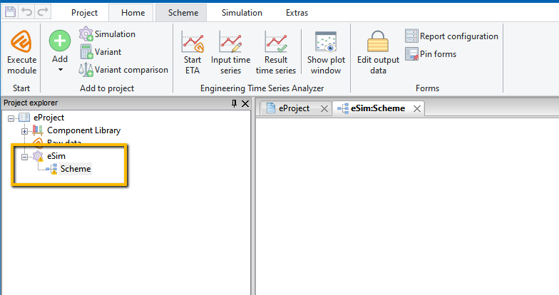
An empty work surface appears on the right side. In principle, this workspace can display two different views, the scheme view and the form view.
The scheme view is used to model energy systems by combining and arranging components. The scheme consists of graphically arranged symbols connected with each other by network lines.
Click on the ![]() Scheme node in the Project explorer, and you get the scheme view.
Scheme node in the Project explorer, and you get the scheme view.
The form view serves to input and output data.
This view is obtained by left-clicking on the module nodes or ![]() components below the
components below the ![]() Scheme node in the Project explorer.
Scheme node in the Project explorer.
From the scheme view, the form view of a component can be opened by double-clicking on the respective component.
Modeling an Energy System
In TOP-Energy, an energy system consists of components ![]() . Components are generated from
. Components are generated from ![]() component templates.
component templates.
The Component template library is located in TOP-Energy at the bottom left. It contains the component templates installed by TOP-Energy. You can also save your own components there.
Component templates for an energy system include:
- technical components (e.g., CHP, boiler, air compressor),
- tariffs, and
- demand components.
Component templates already contain a number of default values. If you create concrete components from the templates, you should parameterize them and replace the defaults with the manufacturer’s specifications.
Example
To familiarize you with how TOP-Energy works, the following First Steps will guide you to create a sample project for the energy supply of a building. In it, the heat supply is initially carried out by a district heating supplier. Then alternative variants are worked out and compared with the actual state.
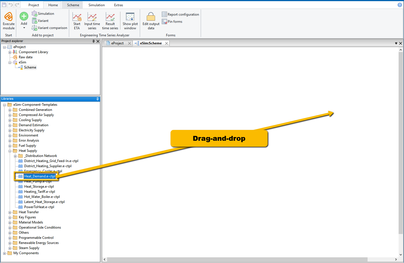
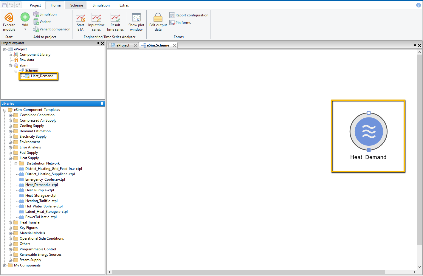
This creates a component from a component template and adds it to the energy system to be analyzed.
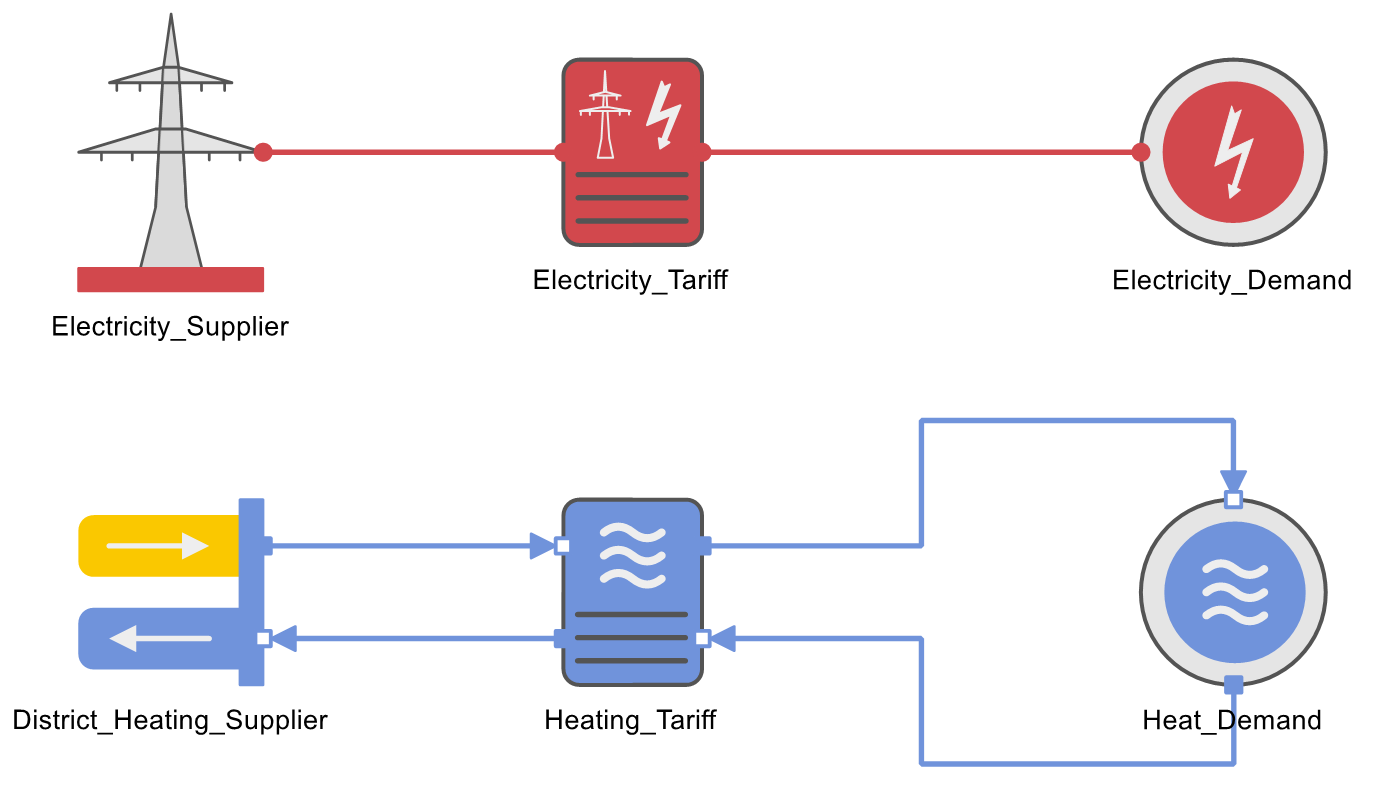
Connecting Components to Networks
Connect the components to form a flow chart. The connections between the components represent energy and material flows. Typical media transported via the networks between the components are represented by the material models in TOP-Energy. These are:
- water (thermal fluid, heat medium),
- steam,
- fuel (oil, gas, pellets),
- electricity,
- air (supply air, exhaust gas).
At the edge of the component symbols there are connection points—the input and output pins.

Output pins are filled squares.
In our example, the components are to be combined into a district heating circuit.
Components and captions can be arranged as desired. They can also be rotated via the context menu (to be obtained by right-clicking) and the selection rotate.
Parameterizing Components
- double-click on the corresponding component symbol in the Scheme, or
- select the corresponding
 component in the Project explorer.
Forms are designed as so-called notebooks. A form has several tabs for opening individual form pages.
Starting the Simulation
There are two ways to start a simulation of the created model:
- by right-clicking on
 Simulation in the Project explorer and selecting
  Start simulation or
 - by selecting Simulation (left-clicking) in the Project explorer and then pressing the TOP-Energy application button Execute module in the ribbon.
The solver is selected automatically according to the default setting.
To start the simulation, open the Simulator window (see following figure) by clicking on the ![]() TOP-Energy button.
TOP-Energy button.
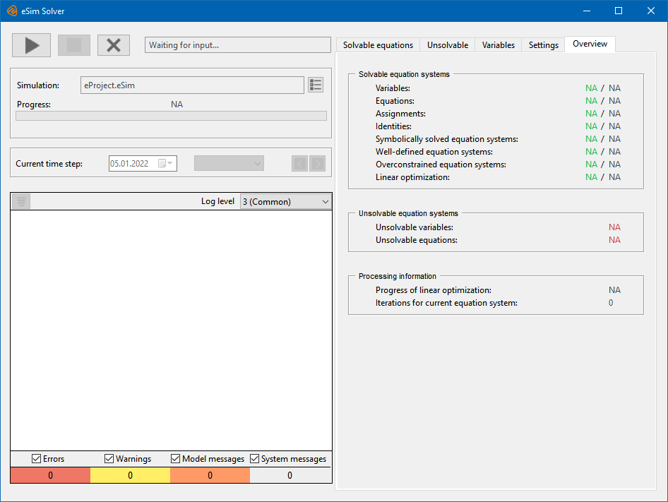
Start the simulation by clicking the start button ![]() .
.
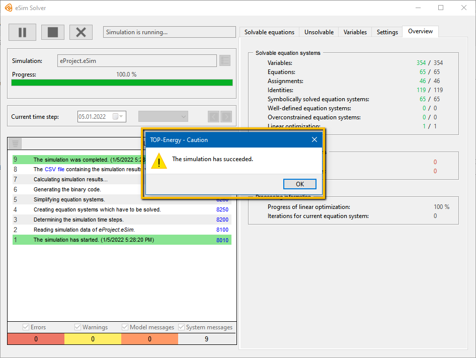
The Simulator window shows the progress of the simulation. After the simulation is complete, a sound is heard, and the following message appears.
Results of the Simulation
Close the eSim solver window and familiarize yourself with the results of the simulation.
Values calculated by TOP-Energy are always in blue lettering.
Click one ![]() component at a time in the project explorer. In the form, switch to the Output data tab and there to the Technical output data or Typical output data sub-tab (see following figure).
component at a time in the project explorer. In the form, switch to the Output data tab and there to the Technical output data or Typical output data sub-tab (see following figure).