Entering Customized Operation Modes
TOP-Energy offers various options to specify the operation modes of the components in the simulation.
In the Simulation form, you can select the Target Function for Optimizing Operations under the tabs General → Simulation and Optimization. For example, Cost of Operation and CO2 Emission are available for selection to achieve the lowest operating costs or CO2 emissions.
However, it is sometimes necessary to specify certain operation modes. There are basically three options: components of the Operational Side Conditions, Programmable Control, and parameterizing the components.
In the following three sections you will learn more about this using examples.
<h2id=”priority”>Operational Side Conditions
The first way to specify operation modes is to use components of the folder Operational Side Conditions. Detailed information on the use of these components can be found in the article Controlling Performance.
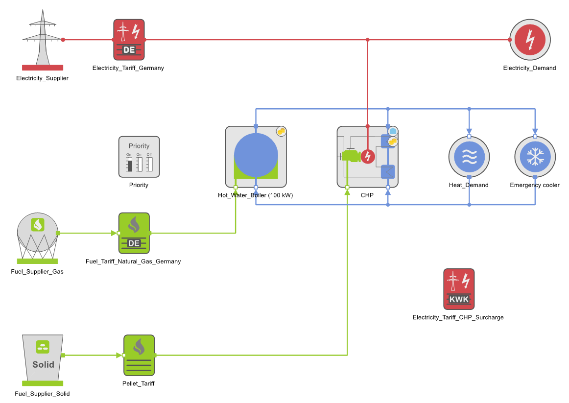
Here you will learn about heat- and current-controlled operation of the cogeneration plant with the component Priority (switch-on sequence). In our example energy system (whose model is shown in variant Var2-CHP electricity controlled of tutorial 60) a variable power and heat demand is covered by a CHP, a hot water Boiler, and an Electricity Supplier.
Current-Controlled
The current-controlled operation of the CHP is realized by the following settings in the component Priority ![]() .
.
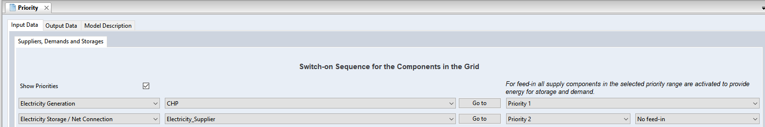
The selection No feed-in for the Electricity Supplier prevents from feeding into the electricity grid (see illustration above).
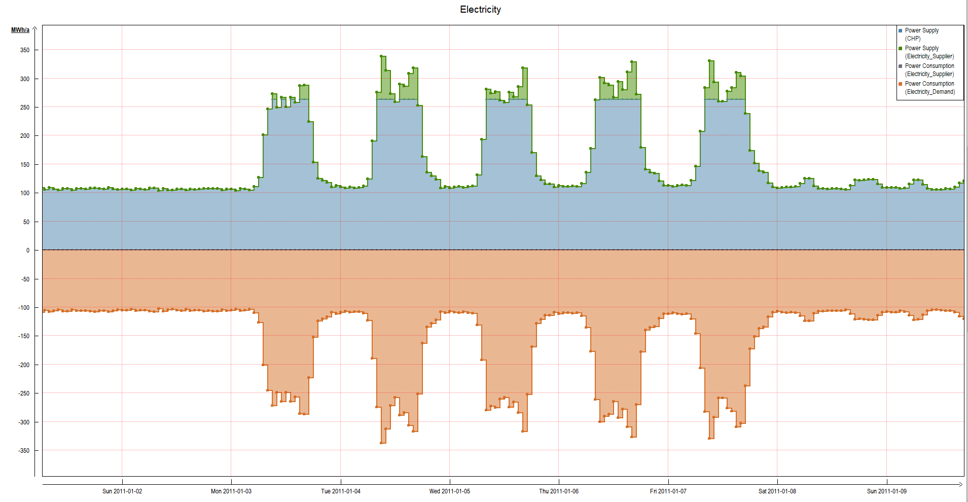
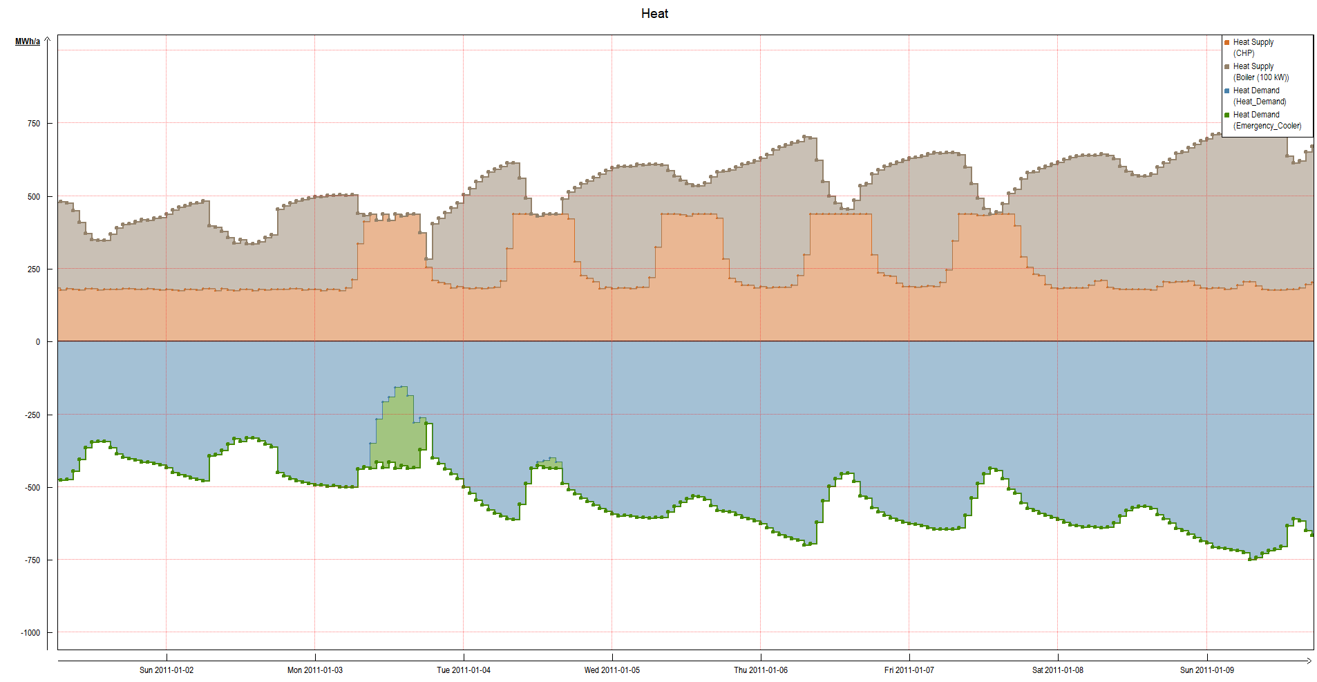
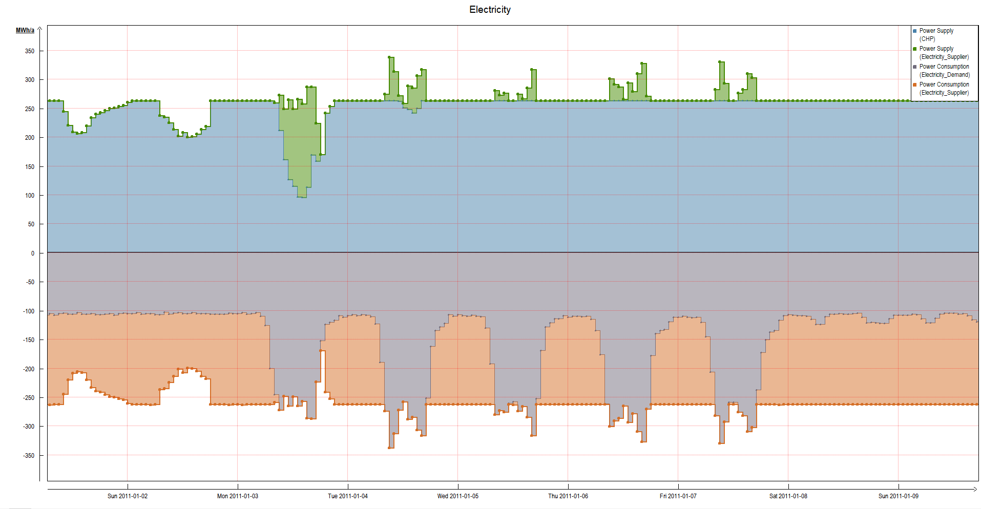
In the following figures, the power curves for electricity and heat show the operation of the CHP determined by the electricity demand based on the specified priority (switch-on sequence). At times of high power and low heat demand, the heat generated by the CHP must be dissipated into the Emergency Cooler (as a component template in the Heat Supply folder).
Heat-Controlled
A heat-controlled operation of the CHP is realized by the following Priority (switch-on sequence).

An emergency cooler can be dispensed with in the case of heat-controlled operation.
The results of the simulation show that the operation of the CHP is dominated by heat demand. At times of low power consumption, the electrical power generated by the CHP is fed into the grid.

Programmable Control
Programmable Control provides the most comprehensive way to specify operation modes. With this component group, the individual control of components can be realized by means of graphic links. For example, programmable controls can be used for storage loading strategies or peak load reduction.
In the following, you will learn how to use the Programmable Control to set a mode of operation using the example energy system introduced in the first section.
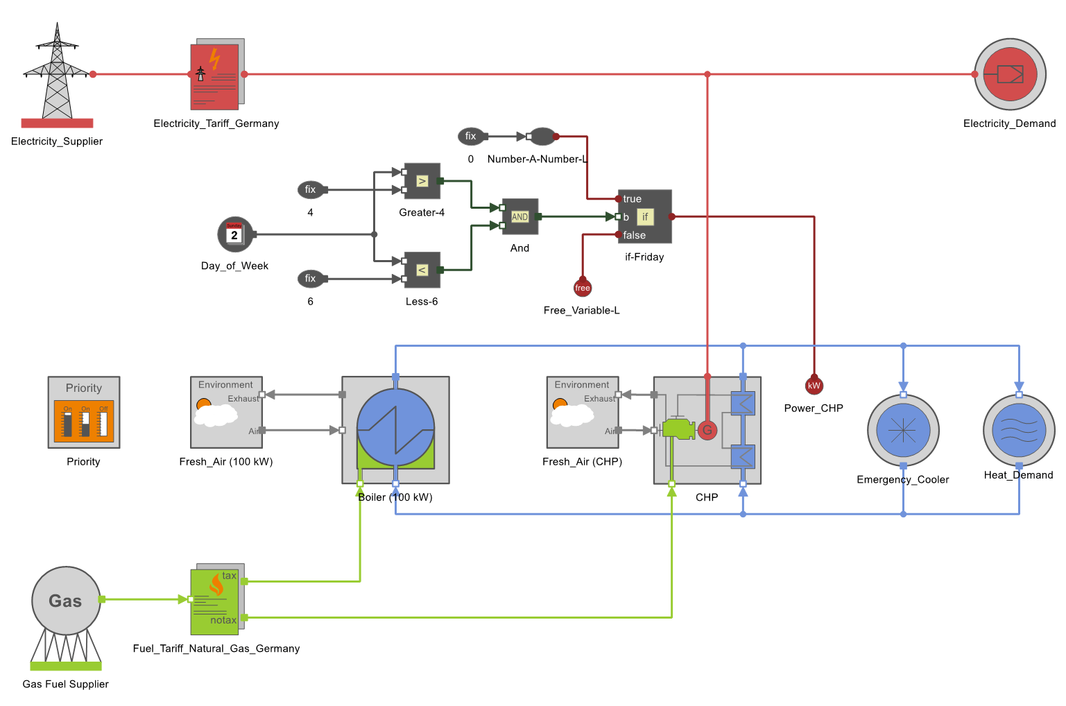
The aim of the Programmable Control shown here is to switch off the CHP every Friday. The CHP unit is accessed via the Power-CHP input. If the branching if-Friday applies, the power of the CHP is set to zero. The weekday query is implemented by the Day_of_Week component, which returns the number of the weekday as an output value.
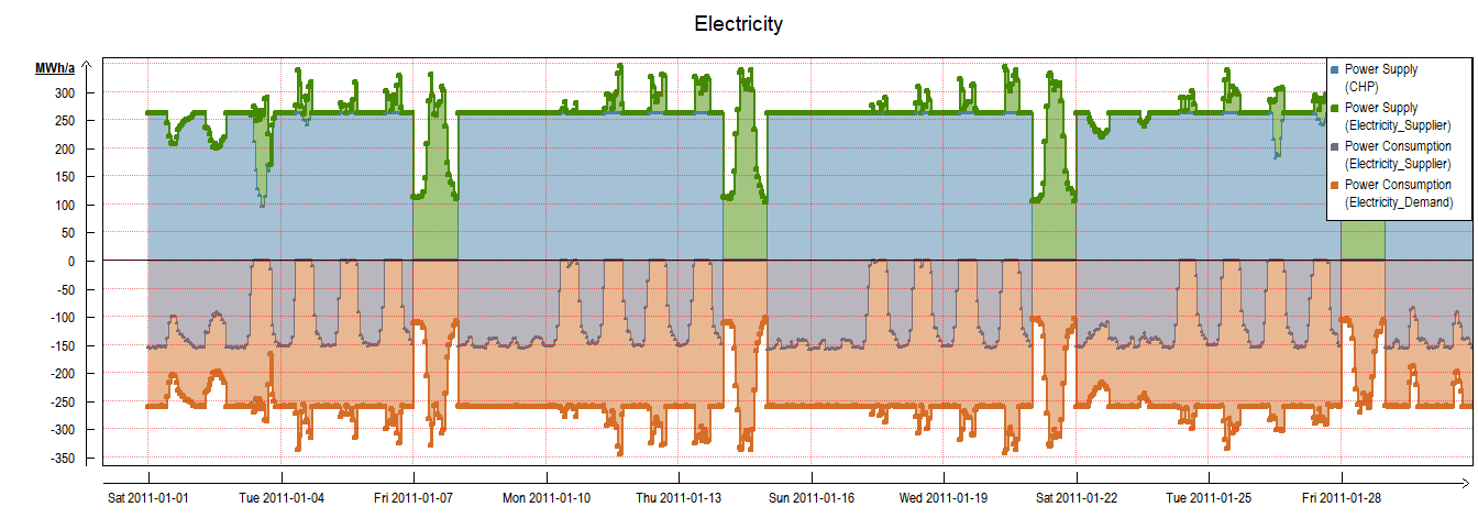
The result of the control can be seen in the electricity curve. In the displayed period of one month, the CHP is switched off four times. At these times, the boiler takes over the provision of heat.
Parameterizing Components
In addition to the above-mentioned two options for setting operation modes, there is also the parameterization of individual components.
For example, the Maximum Power Output can be set to zero at the Electricity Supplier component in order to prevent electricity from being fed into the grid. Another possibility is to limit the Maximum Power Input of the Electricity Supplier. In this way, peak load reduction can be achieved, as explained in the article Avoiding Peak Loads.