Modeling a Heat Recovery Steam Generator (e.g., for combined cycle processes)
Gas and steam turbine power plants (CCGT, combined cycle gas turbines) use the hot exhaust gas from the gas turbine to generate steam in a heat recovery steam generator (also known as a waste heat recovery boiler, WHRB). The two thermal engine processes run one after the other. It is exploited that water can be evaporated at much lower temperatures than those prevailing in the combustion chamber of a gas turbine.
A heat recovery steam generator is modeled in TOP-Energy by interconnecting individual other elements. It consists of at least two heat exchangers (from the component template folder Heat Transfer) and can optionally be equipped with an auxiliary firing system. The Auxiliary fire is created with the component template Hot_Water_Boiler from the component template folder Heat Supply.
Simple Heat Recovery Steam Generator
The following figure shows the interconnection of a gas turbine with a waste heat steam generator. An orange frame surrounds two heat exchangers, which transfer heat energy from the exhaust gas of the gas turbine to the steam generator: The Heat Transfer component template Heat_Extraction_From_Air forms the HT heat recovery boiler, and the Heat Transfer component template Heat_Release_To_Steam forms the evaporator.
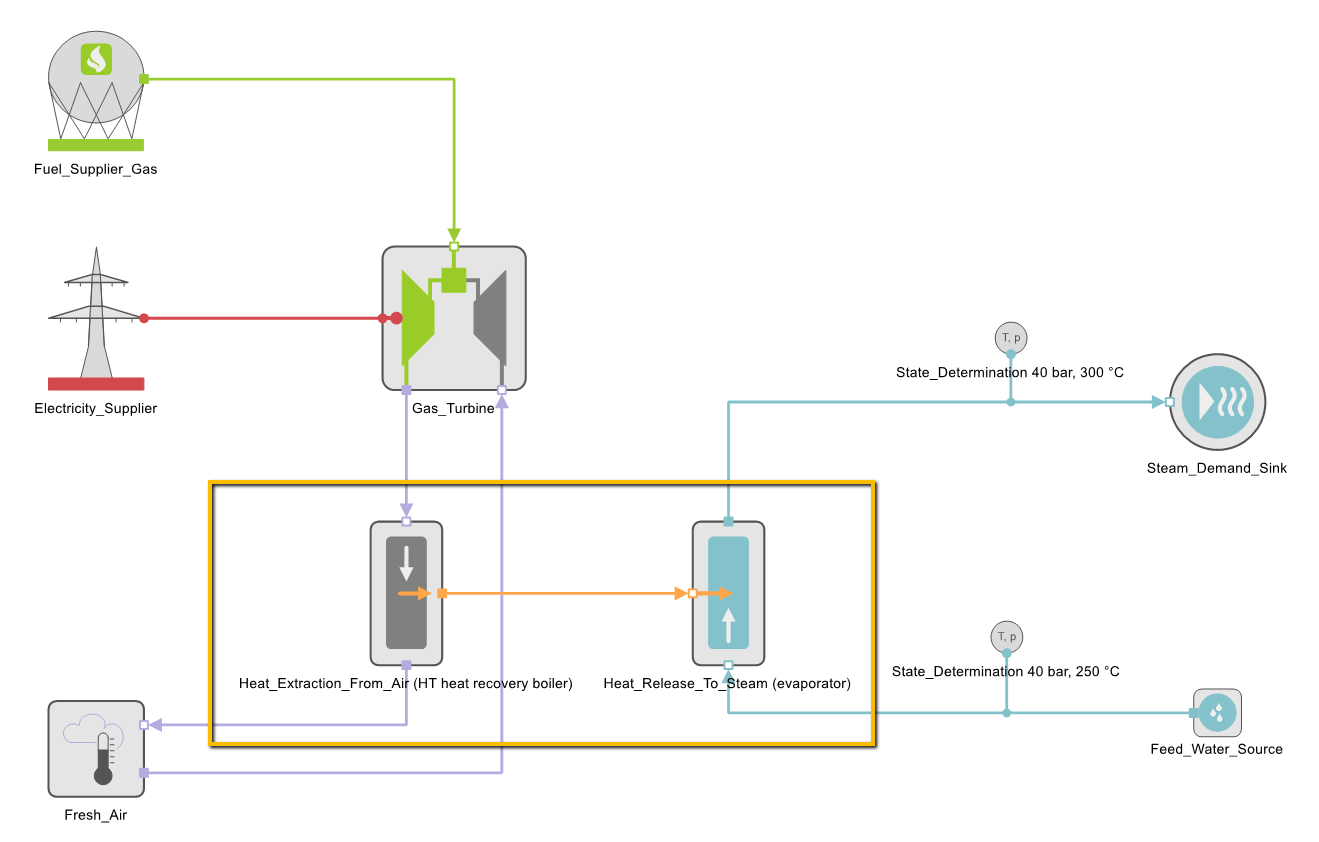
Gas Turbine With Waste Heat Steam Generator
The heat exchanger is parameterized in the two associated components. All heat exchangers are limited by entering the Maximum heat transfer. If different upper barriers are specified in the two heat exchanger halves (here HT heat recovery boiler and evaporator), at most the lower one becomes effective.
In heat exchangers with the heat transfer medium Air, the maximum transferable energy quantity is additionally limited by specifying the Minimum outlet temperature \( T_{air\ out,\ min}\) (or the Maximum outlet temperature in the case of the Heat_Release_To_Air component).
The minimum specific enthalpy \( h_{air\ out,\ min}\) (see equation 1) is calculated from the given Minimum outlet temperature of the heat exchanger (HT Heat recovery boiler). From the minimum specific enthalpy \( h_{air\ out,\ min}\) results the thermal enthalpy flow \( \dot{H}_{air\ out,\ min}\) (see equation 2), which limits the actually escaping enthalpy flow \( \dot{H}_{air\ out}\) (see equation 3). This form of restriction depends on the inlet condition (here: the operation of the gas turbine and its outlet temperature). This is the difference between this method for limiting \( \dot{H}_{air\ out}\) and the specification of Maximum heat transfer.
To parameterize the heat exchangers, the minimum (or maximum) outlet temperatures must be specified. These are usually not technical data, but are system-specific variables. They must first be calculated or estimated externally for the given conditions.
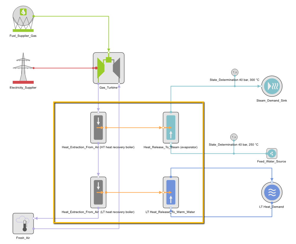
Heat Recovery Steam Generator With Low Temperature Heat Extraction
The modeling of a waste heat steam generator with low temperature heat extraction is also carried out by interconnecting the individual components. The following figure shows a possibility of interconnection. Here, the hot exhaust gas emerging from the gas turbine is used to generate steam. The remaining residual heat of the exhaust gas is used to cover a heat demand at a lower temperature level. For this purpose, the scheme is extended by the component templates Heat_Extraction_From_Air for the LT heat recovery boiler and Heat_Release_To_Warm_Water for the LT heat exchanger.
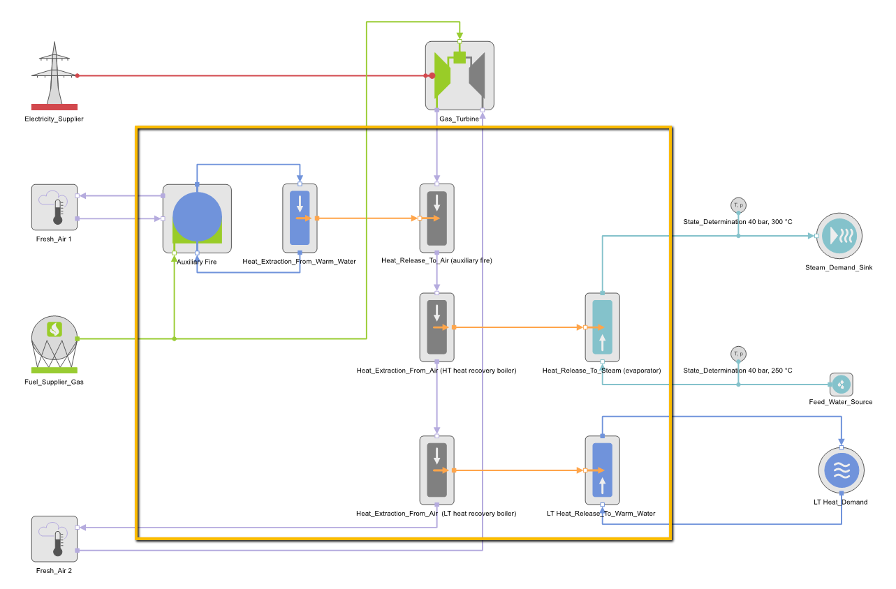
Heat Recovery Steam Generator With Low Temperature Heat Extraction and Auxiliary Fire
In order to achieve greater independence from gas turbine operation, a waste heat steam generator can be operated with an auxiliary firing system. The additional firing raises the temperature level of the exhaust gas stream used and increases the steam generator output.
The following figure shows the scheme with the interconnected components. The Auxiliary fire is modeled in TOP-Energy with three components. The component called Auxiliary fire in the scheme is created using the component template Hot_Water_Boiler. The component Heat_Extraction_From_Water was connected to this, which transfers its heat to the component Heat_Release_To_Air (with the addition (auxiliary fire) in the scheme). The heat transfer here is loss-free. There is no energetic difference to the normally practiced direct firing of the exhaust gas without the heat transfer medium water.
It is not possible to consider the effective increase in heat transfer due to the pinch shift. The heat transfer quantity is always calculated from the potential difference between the incoming and outgoing medium. Therefore, the increase in efficiency of auxiliary firing must be represented indirectly by parameterization of the Auxiliary fire component.
Depending on data situation and operating mode, certain input data must be calculated when parameterizing a heat recovery steam generator. A proposal for parameterization in case that the steam generation capacity (the steam mass flow produced) is known without the use of auxiliary firing, is presented below.
The maximum output of the heat exchangers HT and LT heat recovery boiler differs in the operating modes with and without auxiliary firing. Therefore, the performance of the individual heat exchanger components cannot be limited by specifying a generally valid Maximum heat transfer. The outlet temperature must be selected or calculated according to the amount of energy that can be cooled down.
The outlet temperature of the high-temperature part of the waste heat boiler (HT heat recovery boiler) is determined as in the following equations. GT stands for the exhaust gas flow from the gas turbine, which is at the same time the inlet air flow into the heat input component Auxiliary fire (on top) of the balance scope described by the equations.
The equations refer to the nominal operating condition. The energy balance is formed around the upper part of the heat generators (see following figure).
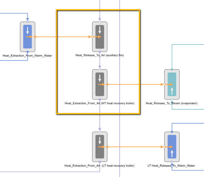
The outlet temperature of the LT heat recovery boiler can be calculated accordingly. Since this is an actual outlet temperature from the technical component, the values may also be known in advance. In the Auxiliary fire component, the auxiliary firing output in rated operation (Nominal thermal capacity) and the losses in the form of Nominal thermal efficiency are specified.