Regenerative Feedwater Preheating (pure heat transfer)
To model regenerative feedwater preheating in TOP-Energy (e.g., with an economizer), the components of Heat Transfer can be used.
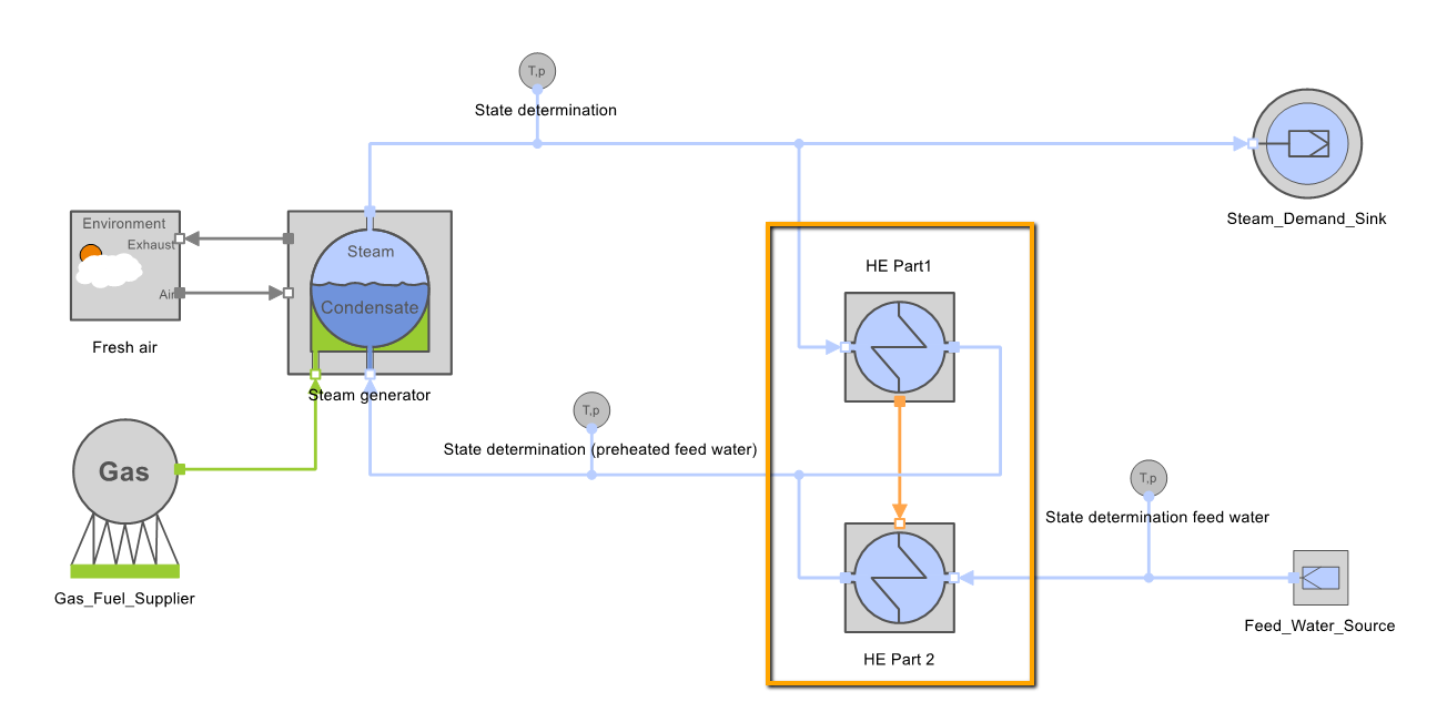
By interconnecting the heat transfer components Heat_Output_Air (exhaust gas) and Heat_Input_Steam (absorption) as shown in the following figure, excess heat from the exhaust gas can be used to preheat the feedwater. HE stands for heat exchanger.

The energy demand is also determined by the specified states before and after the component HE Part 2 in combination with the steam mass flow determined by the optimization. The exhaust gas quantity must always be enough to deliver the required power so that a valid solution for the energy system exists. An example for this is the Tutorial 33 – Two-Stage Steam Power Process.
Feedwater Tanks with Steam Feed (mixture of material flows)
The case of feedwater preheating by an admixed steam flow can also be simulated with the Heat Transfer components. This will be demonstrated using the following example:
In case of a steam admixer for feedwater preheating, exactly enough steam must be withdrawn from the upper line so that the cold feedwater reaches the desired temperature by admixture. Both the mass and energy balance must be met. A storage effect is not taken into account. The balance of an ideal feedwater tank is as follows.

The following figure shows the balance scope of a feedwater tank combined with the TOP-Energy scheme.
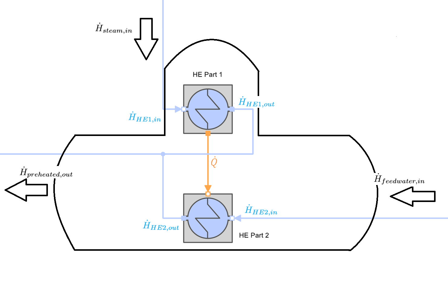
The interconnection is done in TOP-Energy as shown in the figure above. Both conditions are fulfilled in this circuit. The feedwater enters the component HE Part 2 with the specific enthalpy \( h_{feedwater}\) and must be raised to the energetically higher state with the specific enthalpy \( h_{preheated}\). The energy required for this is inevitably extracted from the HE Part 1, which energetically devalues the injected steam from \( h_{steam}\) to \( h_{preheated}\). The defined energy flow and the defined states clearly determine the corresponding mass flow in HE Part 1. This results in the following TOP-Energy model equations:
Balance limit around HE Part 1 or Part 2:

Balance limit around the mixing node:
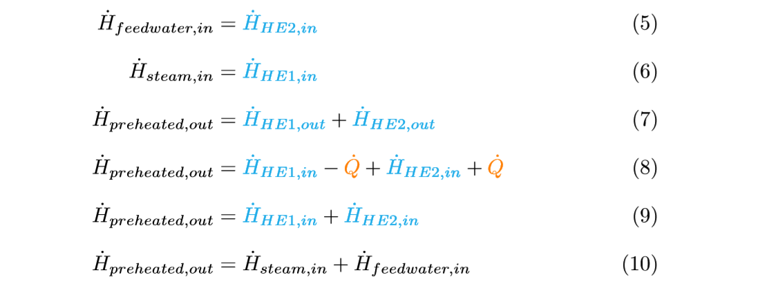
The last equation corresponds exactly to the original energy balance from equation (1). The mass balance can be set up accordingly.