Series and Parallel Connection of Heat Components
In TOP-Energy, heat components can be linked in series or parallel circuits. The special features of both types of connection are explained below, taking into account the energy- and temperature-related input data.
Parallel Connection
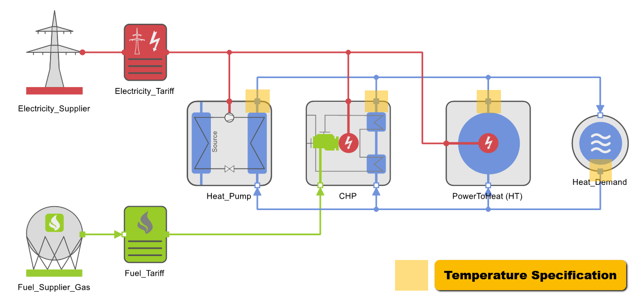
Normally, heat components in TOP-Energy are connected in parallel, because the model equations of the components (with their respective input and output data) are designed for this type of connection. In all heat components, the outlet temperatures (flow temperatures) must be specified under the tab Input data. The following figure shows a parallel connection, which includes one heat demand and three heat generators.
In the figure, the outlet temperature to be entered for each component is marked. During the simulation, the return flow temperatures are calculated by coupling the energy and mass flows and displayed under the tab Output data. In this circuitry, the energetic optimization is not influenced by the default outlet temperatures.
Series Connection
In a series connection, the equations for coupling the energy and mass flows contain less degrees of freedom than in a parallel connection. Therefore, some special features must be taken into account when simulating a series connection. You have the following two options when you parameterize the components. Please note that the second option is preferable.
Specificating the Outlet Temperature
In the first variant, the exit temperatures of all components are entered in the Input data tab before the simulation, as is normally the case (with parallel connection). In the case of a series connection, however, the following problems can occur with this standard parameterization:
In principle, the energetic optimization is influenced by the specification of all outlet temperatures in a series connection. Consequently, the simulation result depends on the specified temperature boundary conditions in the input data. To avoid this, you should set the parameters as described in the following section.
Calculating the Outlet Temperature
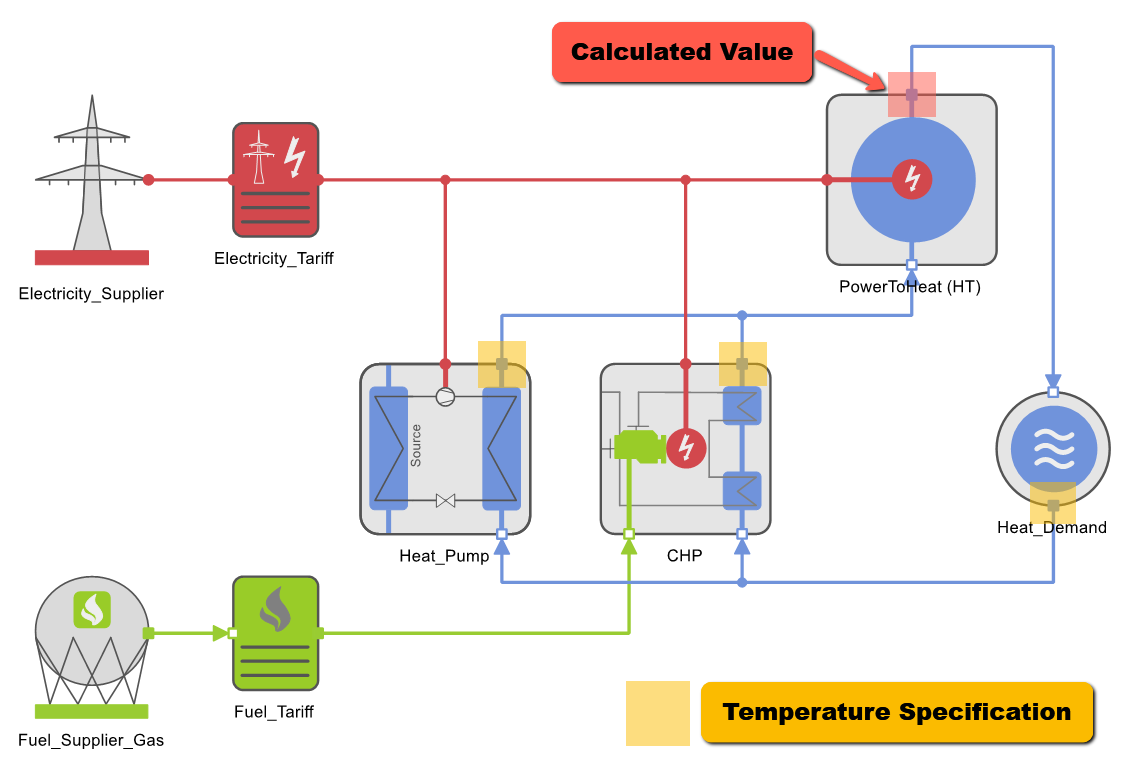
The second – better – variant for simulating a system with series connection allows the simulator to calculate the outlet temperature (flow temperature) of the first component connected in series.
The example system illustrated shows you how to do this. In the example system, the power-to-heat component is connected in series.
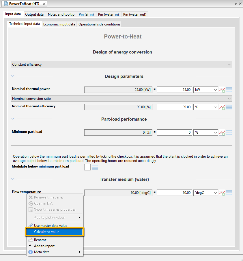
For this component, the input data in the Thermal performance section of the Input data tab page must be set as a calculated value for the flow temperature parameter. This is realized as follows:
This means that both the inlet and outlet temperatures for this component are calculated in the simulation. In this way, as in a parallel connection, the energetic optimization is not influenced by the temperature boundary conditions. This parameterization is therefore recommended for series connection.
Further information can be found in the articles on Tutorial 62–Heat Generators With Different Temperature Levels (series connection) and Tutorial 63–Heat Generators with Different Temperature Levels (parallel connection).


